Design rules for FDM: wall thickness, holes and overhangs
A few design habits make FDM parts stronger, cheaper and easier to print. The figures in this guide are rules of thumb for a typical 0.4 mm nozzle. They are starting points, and a test print confirms them for your part and material.
| Feature | Rule of thumb |
|---|---|
| Wall thickness | At least two nozzle widths: about 0.8-1.2 mm |
| Functional walls | About 1.6-2.4 mm, thicker where loaded |
| Holes | Print slightly small: add about 0.1-0.3 mm |
| Clearance for mating or moving parts | About 0.3-0.5 mm |
| Overhangs | Self-supporting up to about 45 degrees |
| Inside corners | Fillet of 1 mm or more |
| Text and small features | Strokes of about 1 mm or more |
Wall thickness
A wall made of a single line of plastic is fragile. Plan walls at least two nozzle widths thick, which is about 0.8-1.2 mm with a 0.4 mm nozzle. For walls with a function, such as holding a screw or a clip, 1.6-2.4 mm is a better starting point, and loaded areas should be thicker still.
Holes and clearances
Printed holes come out slightly smaller than designed, so add about 0.1-0.3 mm to the diameter when a bolt or pin has to pass through. For two parts that fit together or move against each other, leave a gap of about 0.3-0.5 mm. Confirm with a test fit before you print the whole batch, because the exact value depends on the printer and the material.
Overhangs and supports
Slopes up to about 45 degrees print without help. A flat overhang needs support, which costs time and leaves marks where it is removed. Replace it with a chamfer, or turn the part so that the problem face points upward. Designing a part that needs no supports is the most reliable way to reduce both cost and surface marks.
Orientation and strength
Plan the load along the layers, not across them, because the bond between layers is the weakest part of the structure. A long part that carries a bending load can be split in two and joined, or printed in another orientation. Our article on how FDM works explains why layers behave this way.
Corners and fillets
Sharp inside corners concentrate stress, and that is where printed parts usually crack. A fillet of 1 mm or more spreads the load and makes the part noticeably tougher at no extra cost.
Small features and text
A feature narrower than the nozzle line will not print. Raised or engraved text needs strokes of about 1 mm or more to be readable, and a bold, simple font works best. If a detail is smaller than that, make it larger, or add it later by painting or marking.
Threads and inserts
Printed threads work for M6 and larger and for parts that are screwed together only a few times. For smaller screws or repeated assembly, heat-set brass inserts give a much stronger thread, and the hole for the insert is easy to design.
Example: improving a simple bracket
Take a bracket with 0.8 mm walls, a sharp inside corner, a flat overhang under the arm and an 8.0 mm hole for a pin. Thicken the walls to 2 mm where the screw sits, add a 1 mm fillet to the corner, replace the flat overhang by a 45 degree chamfer and open the hole to 8.2 mm. None of these changes alters the function, yet the bracket becomes stronger, needs no supports and fits the pin on the first try.
Use small test prints
When a fit matters, print a small coupon first: a short strip with a few holes of different diameters and a pair of mating pieces with different gaps. It takes a fraction of the time of the real part and tells you the exact allowance for your printer and material.
Designing for assembly and repair
Printed parts are often one piece of a larger assembly, so it pays to think about how they go together. Add small alignment features such as pins and recesses so that parts find their position by themselves. Split a complex part into two simple ones if that removes supports or lets you print each piece in its best orientation.
If you use a snap fit, remember that the arm is weakest when it is printed standing upright, because it then bends across the layers; print it flat on the bed or on its side so that it bends along the layers, and that PETG and ABS survive repeated bending better than PLA. Design the part so that a worn or broken piece can be replaced without throwing away the whole assembly.
Checklist before you send the file
- Walls are at least 0.8-1.2 mm, and thicker where loaded.
- Holes have an allowance, and mating parts have a clearance.
- Overhangs are below about 45 degrees or replaced by chamfers.
- The load runs along the layers.
- Inside corners are rounded.
- Small features and text are large enough.
When the model is ready, prepare the file and send it to us. We review it for printing before we start and tell you if something should change.
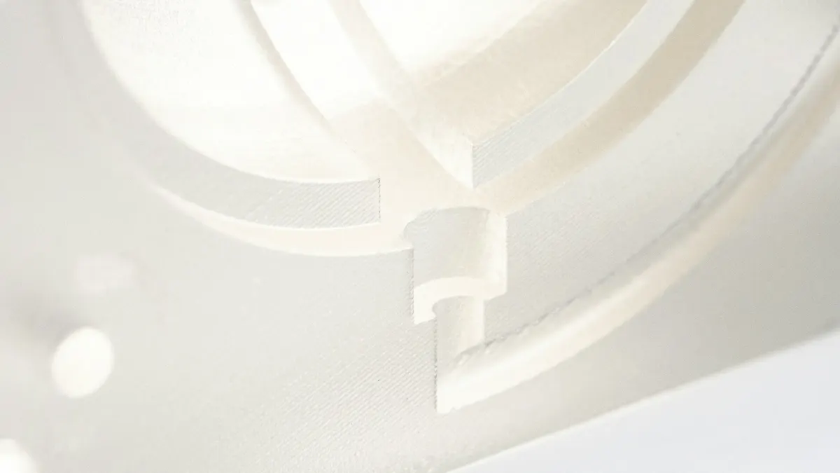
Cover photo: Spencer Liao(opens in a new tab) on Unsplash(opens in a new tab).